spacer spacer spacer spacer spacer
Home

Index


Test machines


Uniaxial
Multi-axis
Torsion machines
Component test
Resonant HCF
Servo-hydraulic
Servo-pneumatic
Steering column
Second user

Test ancillaries


Servo-control
Data acquisition
Hydraulics
Specimen fixing
Environmental

Measurement


Displacement
Gas flow

Production


Bespoke machines

Services


Strain gauge
Calibration
Electronic assembly

Miscellaneous


Actuators
I/O cards
Quality


12bit Servo controller and data acquisition unit

A powerful, value for money solution for machine control and data acquisition
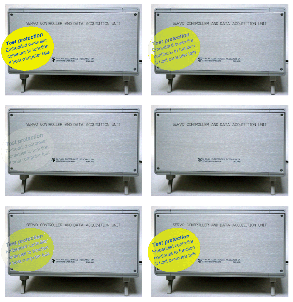
A powerful, value for money solution for machine control and data acquisition PC Software
  • Written in C (utilising National Instruments LabWindows™ CVI libraries).
  • The Test control windows for dynamic fatigue and tensile testing (below right) feature a selectable digital control parameter. For materials testing this could be load, strain or displacement.
  • User selectable sine, triangle, square waves, ramp rate and frequency or control from external input.
  • Test waveforms defined in Excel™* may be imported into the package.
  • The servo controller is compatible with Lloyd Instruments' Nexygen™ software* which can be used to drive tensile tests and to analyse and present data.


  • Si-Plan data storage format allows:
  • Import into Excel™*.
  • Import into nCode Testlab software* a powerful package for test laboratory data analysis:
  • Load controlled (S/N) specimen test analysis
  • Strain controlled (E/N) specimen test analysis
  • Tensile test analysis
  • Data basing facility
  • Associated nCode software products
      FATIMAS
      Fe-Fatigue
      MSC.Fatigue
      PTC Fatigue Adviser

    * This software is not included in the standard package price.
    Description
    The Si-Plan Electronics Research 779 series servo controller and data acquisition unit is a flexible, stand-alone system, designed for use with the company's range of test machines and as a retro-fit controller to existing machine frames from other manufacturers. The servo control is implemented on the embedded processor. The control algorithm is user accessible via the PC interface.

    Features
  • 1 channel servo control with selectable feedback from 5 inputs.
  • Transducer linearisation facility on all channels.
  • Heating/cooling demand signal.
  • Runs in Windows™ operating systems (2000, NT, 95 and 98).
  • Based on 32 bit ARM® RISC processor.
  • In the event of host computer failure, the embedded controller continues to operate providing test integrity.
  • Data acquisition on up to 8 channels (single ended, 12 bit).
  • When required, a 16 bit data acquisition card can be fitted to the PC to run alongside the existing software for greater resolution and logging frequency.
  • 24 digital I/O.
  • Monitor points conditioned to ±10 volts.
  • Adaptive control: automatically adjusts the servo command to achieve required performance, updating at each cycle.
  • Software test protection trips.
  • Optional hardware test protection trips.
  • Test control Dynamic test control window
    Tensile test control window Up
    Dynamic test control window
    Left Tensile test control window
    Test control software
    The software is a versatile package written primarily for fatigue testing. Data can be displayed as
  • XT graph
  • XY graph
  • DPMs (as many as required)

  • Data sources can be selected from:

    Load* Error (demand - feedback)
    Load demand* Integrated error
    Load min* Differentiated error
    Load max* Valve drive

    (*Similarly for Displacement, Strain and optional input, eg Load x 10.)

    XT graph and logger
    Select up to 4 channels for XT graph (below) and data recording.
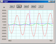
    XT graph
    Use Spool on the Logger window to set up a file for data logging to disc (CSV format).

    XY graph
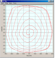
    XY Grapg Select 2 channels for the XY graph display (right).
    DPM
    Dpm
  • Display as many DPMs as required.
  • Drag corner to enlarge or shrink.
  • Use Setup to select the channel.


  • Defining the waveform amplitude
    The amplitude of the waveform is defined by specifying combinations of two parameters from Wave form generation
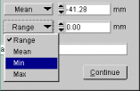
  • Mean
  • Minimum
  • Maximum
  • Range

  • Use the drop down menus (right) on the test control window to select the parameters.

    Calibration
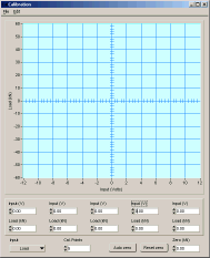
    Calibration
    Adjust settings for the 4 control channels.
  • Enter adjustments for up to 5 points to correct transducer non-linearity
  • Use Auto zero to eliminate small variances due to grips.

  • Programme suite also includes Trips setup and PID setup.
    Typical PC specification
  • Pentium III 600Mhz processor or better.
  • 64Mb memory.
  • COM port 1 available.
  • CD drive for programme installation.
  • Graphics card: 1024 x 768 @ 256 colours.
  • Special requirements
    Si-Plan Electronics Research Ltd has a history of building special rigs to customer requirements. The company is able to carry over this service to its standard product range, giving a flexibility to meet the needs of each customer - and in-house CAD systems and CNC machining mean a realistic delivery time will be achieved.

    Updated 20 April 2005